Serial Interfaces - I²C
Overview
- Inter-Integrated Circuit
- Serial data bus developed by Phillips in 1982
- Mainly: Communication between a controller and peripherals on a printed circuit board
- only two signal wire are needed:
- SCL: slave clock
- SDA: slave data
- designed for short cable length
- technically identical bus standard: SMB (System Management Bus), TWI (Two-Wire Interface)

- typically: one master per I²C bus (multi-master systems seldom used)
- multiple slaves
- SDA and SCL lines are held on H level by a pullup resistor
- Master and slaves can pull SDA and SCL lines to GND.
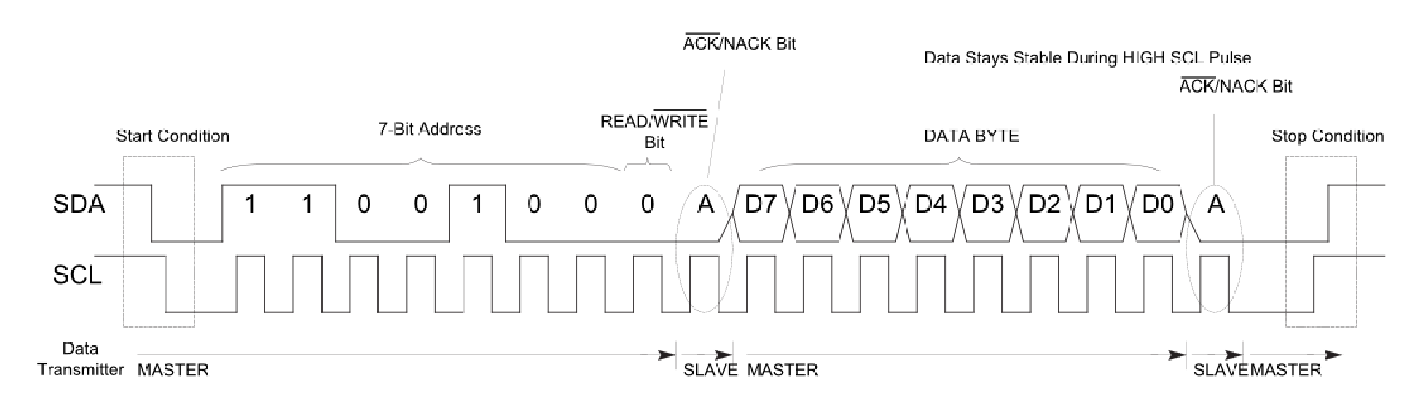
- Master starts communication by sending the START sequence: SDA line is pullup down before SCL line.
- Each slave has a unique 7-bit address (MSB first)
- Master sends the address of the corresponding slave.
- The R/W bit is added to define wether data is written or read to the slave.
- R/W = 0 → Write data to the slave
- R/W = 1 → Read data from the slave
- The 7-bit address together with the R/W bit is defined a the 8-bit address. Make sure to find out the correct address in the datasheet.
8-bit address = ((7-bit address) << 1) + (R/W bit) - The slave sends an acknowledgement by pullup down the SDA line. If no slave with this address is present, the communication stops, until the master gives up.
- Depending on the R/W bit an arbitrary number of bytes is transferred. The receiver sends an acknowledgement after each byte.
- The communication is stopped by the master sending the stop condition: SCL line is released before the SDA line.
I²C Slave Example: Si7021
Si7021
- Humidity and temperature sensor
- Simple connection interface: VDD, GND, SDA, SCL
- very low standby current: 60 nA
- 7 bit address: 0x40
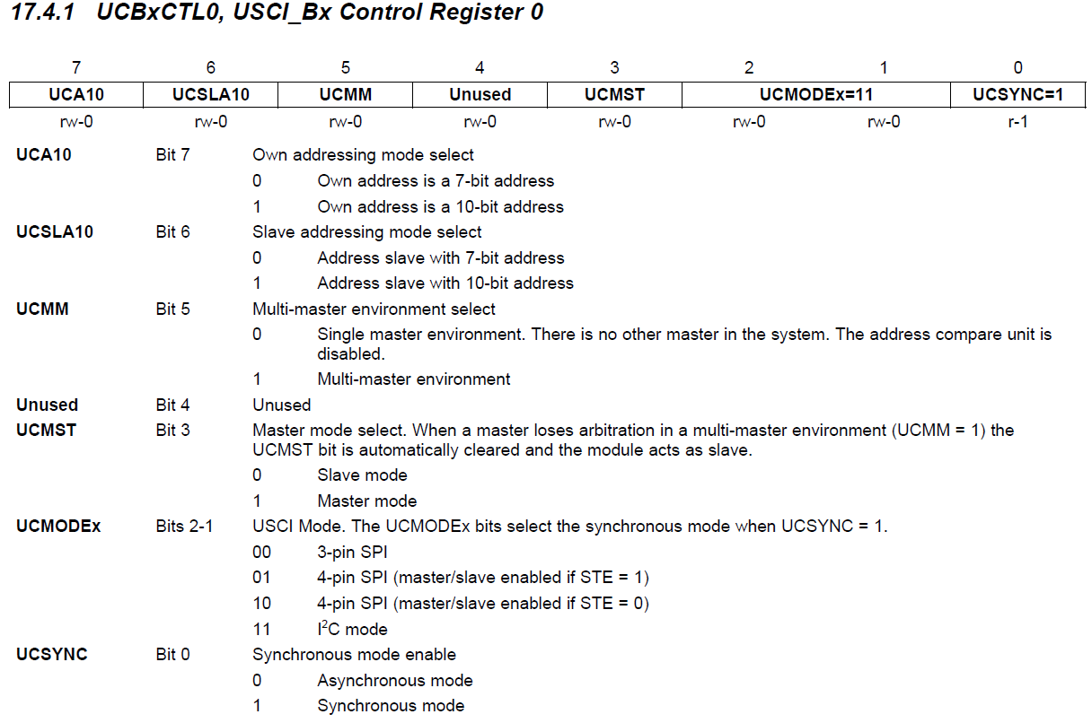
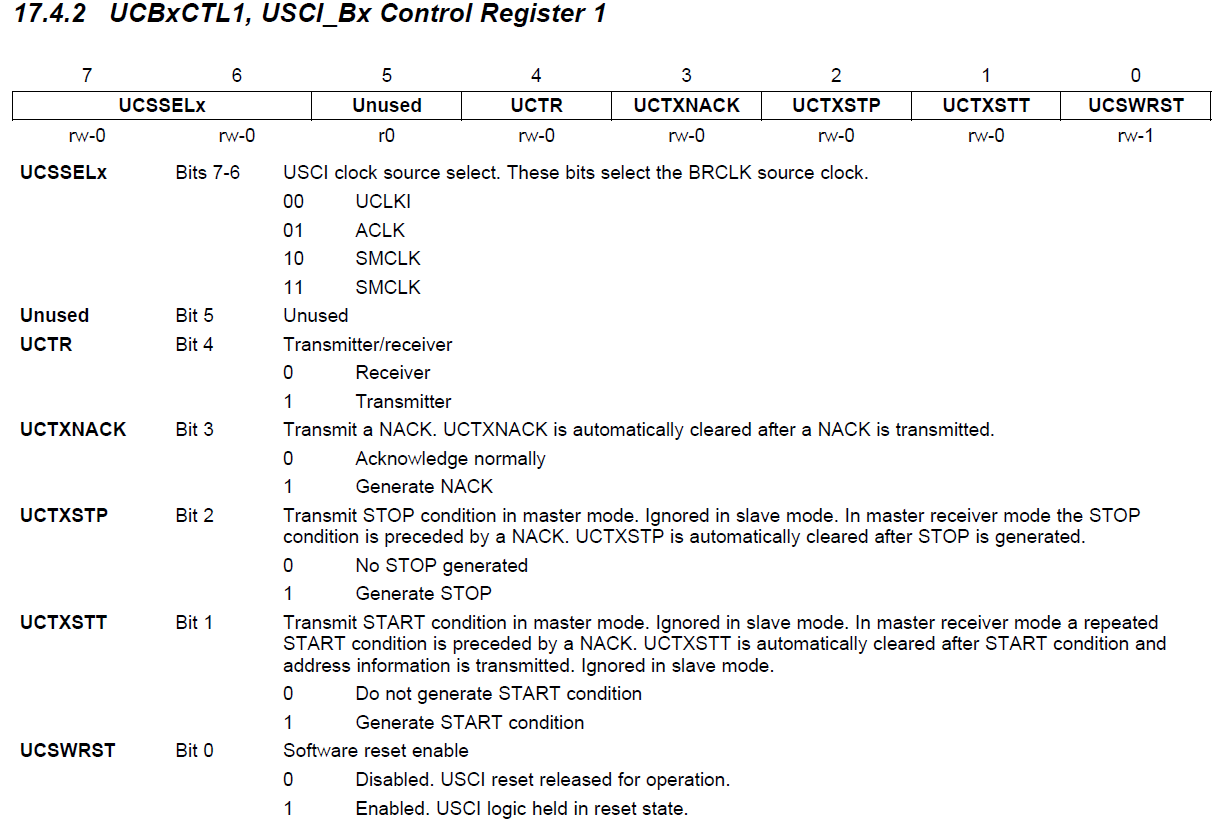
MSP430 Registers
I²C Library
- Download: i2c_modified.zip
- I²C with behavior with ACK is rather complex.
- Flag polling can freeze program, when slave does not respond.
- I²C library uses the WDT to generate a timeout and ensure no program freezing.
- I²C communication is aborted in case of a timeout.
- A return value is given on abort.
Check Si7021 Presence
#include <msp430.h>
#include <stdint.h>

#include "pins.h"
#include "term.h"
#include "i2c.h"

int main(void) {
    WDTCTL = WDTPW | WDTHOLD;    // stop watchdog timer

    p_setup();
    i2c_init();
    term_init();
    term_wait_and_clear();

    while (1) {
        uint8_t data[2];
        uint8_t result = i2c_read(0x40, data, 1);

        term_log_begin();
        term_print("I2C read on address 0x40: ");
        term_test_result(!result);
        term_end();

        p_delay_ms(1000);
    }
}
- A read request is attempted on address 0x40.
- If result == 1, there is a error on the I²C bus and the I²C did not respond.
- When running the program, the debug terminal output should return a green P.
- Removing the WuRx shield and disconnecting the Si7021 should result in a red X.
Reading Temperature Value
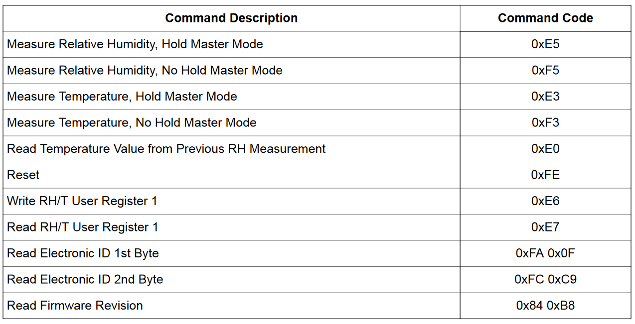
- Note!: Some WuRx shield have the HTU21D populated instead of the Si7021. Most I²C registers are identical, but the timing is slower.
- For the following programs the timing values of the HTU21D will be used to ensure compatibility.
- The temperature measurement is stated by sending the I²C command 0xF3. A pointer is to forward the message to the library.
- The program must wait 70 ms to ensure complete measurement.
- The result is read by an I²C interaction directly into a 16 bit integer.
- Because the data is read MSB first from the sensor, but MSP430 is storing LSB first, the bytes are swapped with a MSP430 library function.
- The raw data can be print over the debug terminal:
Info
This source code is only for your information. You are missing essential files to run the program on your device. Nevertheless, study the code carefully.
#include <msp430.h>
#include <stdint.h>
#include "pins.h"
#include "term.h"
#include "i2c.h"
int main(void) {
WDTCTL = WDTPW | WDTHOLD; // stop watchdog timer
p_setup();
i2c_init();
term_init();
term_wait_and_clear();
while (1) {
// I²C Check
uint8_t data[2];
uint8_t result = i2c_read(0x40, data, 1);
term_log_begin();
term_print("I2C read on address 0x40: ");
term_test_result(!result);
term_end();
// Temperature
uint8_t data2 = 0xF3;
i2c_write(0x40, &data2, 1);
p_delay_ms(70);
uint16_t raw_data;
i2c_read(0x40, (uint8_t *) &raw_data, 2);
raw_data = __swap_bytes(raw_data);
term_log_begin();
term_print("raw data T=0x");
term_hex(raw_data, 4);
term_end();
p_delay_ms(1000);
}
}