MSP430 Pinmapper
Motivation
- For changing the state and the function of MSP430's pins several registers are used. Depending on the port of the used pin the register changes.
- Changing registers bits with the help of bit manipulation inside your program is not a good practice:
- Imagine you want to change a MSP430 pin to another.
- E.g. the same function is preserved, but PCB routing is much easier.
- So all occurrences of this bit register changes must be applied inside the program.
- Making mistakes when changing pins is typical and leads to bugs inside your program.
- The solution is a so-called hardware abstraction layer (HAL):
- In other words: A module that provides abstracted functions for the pin activities.
- E.g. a function
pin_led_h()instead of writingP1OUT |= BIT0. - Or
pin_button_is_pressed()instead of writingP1IN & BIT3.
- Providing these functions can be done by writing a module. But this chapter describes another way to implement such a HAL for the MSP430's pins.
- When calling a function in C, the MSP430 needs additional clock cycles to enter and leave the function.
- When using a macro the source code is pasted into the file before compiling.
- Because pin functions often only need a single instruction, the memory allocation is identical or less.
- The following example shows that 8 additional clock cycles are needed, when using a function instead of a macro.
- The Timer A0 is used to count the number of clock cycles used to run a instruction.
Cycle counter: Calling function vs. using a macro
void tick() {
  TA0CTL = TASSEL_2 + MC_2 + TACLR;
}

uint16_t tock() {
  TA0CTL = 0;
  return TA0R - 12;
}

void func_normal() {
  P1OUT |= BIT0;
}

#define MACRO() (P1OUT |= BIT0)

int main(void) {
  ...
  tick();
  t1 = tock(); // 0

  tick();
  func_normal();
  t2 = tock();  // 12

  tick();
  MACRO();
  t3 = tock();  // 4
}
Using the MSP430 Pinmapper
Introduction
- The proposed solution for the described HAL is the MSP430 Pinmapper, which can be found under: http://robert-fromm.info/msp430-pinmapper/
- This is a GUI running inside the browser and is used to generate a header file containing macros to control the pins.
Example
- As a first example the following program should be implemented:
Write a program that loop through the RGB LED colors: red, green and blue, when the button on the Launchpad was pressed.
Use the generated pins.h as a HAL. - The following JSON code needs to be pasted into the MSP430 PinMapper in order to restore the project.
{"definitions":[{"name":"LED_R","pin":"P2.1","functions":[{"dir":"1","out":"0","sel":"-","sel2":"-","in":"-","ren":"-","ie":"-","ies":"-","ifg":"-","name":"setup","type":"set"},{"dir":"-","out":"1","sel":"-","sel2":"-","in":"-","ren":"-","ie":"-","ies":"-","ifg":"-","name":"h","type":"set"},{"dir":"-","out":"0","sel":"-","sel2":"-","in":"-","ren":"-","ie":"-","ies":"-","ifg":"-","name":"l","type":"set"}]},{"name":"BTN","pin":"P1.3","functions":[{"dir":"0","out":"1","sel":"-","sel2":"-","in":"-","ren":"1","ie":"1","ies":"0","ifg":"0","name":"setup","type":"set"},{"dir":"-","out":"-","sel":"-","sel2":"-","in":"?","ren":"-","ie":"-","ies":"-","ifg":"-","name":"val","type":"get"},{"dir":"-","out":"-","sel":"-","sel2":"-","in":"-","ren":"-","ie":"-","ies":"-","ifg":"?","name":"ifg","type":"get"},{"dir":"-","out":"-","sel":"-","sel2":"-","in":"-","ren":"-","ie":"-","ies":"-","ifg":"0","name":"ifg_clr","type":"set"}]}],"device":"MSP430G2553","xinXout":true,"filename":"pins.h","prefix":"p_","dcoCalibration":true,"delayFunctions":true,"doxygenHeader":"@file pins.h\n@author Robert Fromm\n@date 07.12.2020\n\nThis file is generated by the MSP430 Pinmapper.\nCopy the following JSON code into Pinmapper program to edit project."}
- Restore the project and generate the code at the bottom.
- Additional feature of the Pinmapper Code:
-
DCO Calibration
- If the checkbox DCO Calibration inside the Output Settings is ticked the DCO calibration is performed by the setup function.
- In order to set the DCO frequency a special symbol needs to defined.
- Project Explorer → Right click on current workspace → Properties
-
Build → MSP430 Compiler → Predefined Symbols → Add a predefined name:
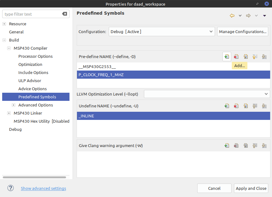
- The following clock frequency and resulting symbols are allowed:
Clock frequency Symbol 1 MHz P_CLOCK_FREQ_1_MHZ8 MHz P_CLOCK_FREQ_8_MHZ12 MHz P_CLOCK_FREQ_12_MHZ16 MHz P_CLOCK_FREQ_16_MHZ- One of these symbols needs to be defined, or a compile error will be thrown.
-
- Delay Functions
- If the checkbox DCO Calibration inside the Output Settings is ticked delay function will be added.
- Because the delay of the function
__delay_cyclesis dependent on the DCO frequency the two macro are defined. p_delay_us()to delay a number of microsecondsp_delay_ms()to delay a number of milliseconds- The constant
P_CLOCK_FREQ_MHZis used as a factor. This constant is defined, when the DCO calibration is performed.
- Setup Function
- The setup function
p_setup()should be called, inside the main program. - The function performs the DCO calibration, if ticked.
- Calls all setup routines of the pins.
- Disables all unused pins of the microcontroller by enabling the internal pulldown resistor.
- The setup function
Question
Restore the project by copying the JSON code into the MSP430 Pinmapper.
Add the pin definition for the green and the blue LED. Generate the output code and add the pins.h file into your project.
Write a main program to loop through the LED colors, when the button was pressed. Use interrupts and enter the LPM.
Solution
pins.h
/**
* @file pins.h
* @author Robert Fromm
* @date 07.12.2020
*
* This file is generated by the MSP430 Pinmapper.
* Copy the following JSON code into Pinmapper program to edit project.
* {"definitions":[{"name":"LED_R","pin":"P2.1","functions":[{"dir":"1","out":"0","sel":"-","sel2":"-","in":"-","ren":"-","ie":"-","ies":"-","ifg":"-","name":"setup","type":"set"},{"dir":"-","out":"1","sel":"-","sel2":"-","in":"-","ren":"-","ie":"-","ies":"-","ifg":"-","name":"h","type":"set"},{"dir":"-","out":"0","sel":"-","sel2":"-","in":"-","ren":"-","ie":"-","ies":"-","ifg":"-","name":"l","type":"set"}]},{"name":"LED_G","pin":"P2.3","functions":[{"dir":"1","out":"0","sel":"-","sel2":"-","in":"-","ren":"-","ie":"-","ies":"-","ifg":"-","name":"setup","type":"set"},{"dir":"-","out":"1","sel":"-","sel2":"-","in":"-","ren":"-","ie":"-","ies":"-","ifg":"-","name":"h","type":"set"},{"dir":"-","out":"0","sel":"-","sel2":"-","in":"-","ren":"-","ie":"-","ies":"-","ifg":"-","name":"l","type":"set"}]},{"name":"LED_B","pin":"P2.5","functions":[{"dir":"1","out":"0","sel":"-","sel2":"-","in":"-","ren":"-","ie":"-","ies":"-","ifg":"-","name":"setup","type":"set"},{"dir":"-","out":"1","sel":"-","sel2":"-","in":"-","ren":"-","ie":"-","ies":"-","ifg":"-","name":"h","type":"set"},{"dir":"-","out":"0","sel":"-","sel2":"-","in":"-","ren":"-","ie":"-","ies":"-","ifg":"-","name":"l","type":"set"}]},{"name":"BTN","pin":"P1.3","functions":[{"dir":"0","out":"1","sel":"-","sel2":"-","in":"-","ren":"1","ie":"1","ies":"0","ifg":"0","name":"setup","type":"set"},{"dir":"-","out":"-","sel":"-","sel2":"-","in":"?","ren":"-","ie":"-","ies":"-","ifg":"-","name":"val","type":"get"},{"dir":"-","out":"-","sel":"-","sel2":"-","in":"-","ren":"-","ie":"-","ies":"-","ifg":"?","name":"ifg","type":"get"},{"dir":"-","out":"-","sel":"-","sel2":"-","in":"-","ren":"-","ie":"-","ies":"-","ifg":"0","name":"ifg_clr","type":"set"}]}],"device":"MSP430G2553","xinXout":true,"filename":"pins.h","prefix":"p_","dcoCalibration":true,"delayFunctions":true,"doxygenHeader":"@file pins.h\n@author Robert Fromm\n@date 07.12.2020\n\nThis file is generated by the MSP430 Pinmapper.\nCopy the following JSON code into Pinmapper program to edit project."}
*/

#ifndef PINS_H_
#define PINS_H_

#if defined P_CLOCK_FREQ_1_MHZ
#define P_CLOCK_FREQ_MHZ 1
#elif defined P_CLOCK_FREQ_8_MHZ
#define P_CLOCK_FREQ_MHZ 8
#elif defined P_CLOCK_FREQ_12_MHZ
#define P_CLOCK_FREQ_MHZ 12
#elif defined P_CLOCK_FREQ_16_MHZ
#define P_CLOCK_FREQ_MHZ 16
#else
#error "No constant P_CLOCK_FREQ_x_MHZ is defined. Cannot perform DCO calibration."
#endif

// PORT 1
#define P_BTN BIT3
#define P_PORT1_UNUSED (BIT0 + BIT1 + BIT2 + BIT4 + BIT5 + BIT6 + BIT7)

// PORT 2
#define P_LED_R BIT1
#define P_LED_G BIT3
#define P_LED_B BIT5
#define P_XIN BIT6
#define P_XOUT BIT7
#define P_PORT2_UNUSED (BIT0 + BIT2 + BIT4)

// PORT 3
#define P_PORT3_UNUSED (BIT0 + BIT1 + BIT2 + BIT3 + BIT4 + BIT5 + BIT6 + BIT7)

// LED_R @ P2.1
#define p_led_r_setup() ({P2OUT &=~ P_LED_R; P2DIR |= P_LED_R;})
#define p_led_r_h() ({P2OUT |= P_LED_R;})
#define p_led_r_l() ({P2OUT &=~ P_LED_R;})

// LED_G @ P2.3
#define p_led_g_setup() ({P2OUT &=~ P_LED_G; P2DIR |= P_LED_G;})
#define p_led_g_h() ({P2OUT |= P_LED_G;})
#define p_led_g_l() ({P2OUT &=~ P_LED_G;})

// LED_B @ P2.5
#define p_led_b_setup() ({P2OUT &=~ P_LED_B; P2DIR |= P_LED_B;})
#define p_led_b_h() ({P2OUT |= P_LED_B;})
#define p_led_b_l() ({P2OUT &=~ P_LED_B;})

// BTN @ P1.3
#define p_btn_setup() ({P1OUT |= P_BTN; P1DIR &=~ P_BTN; P1REN |= P_BTN; P1IES &=~ P_BTN; P1IFG &=~ P_BTN; P1IE |= P_BTN;})
#define p_btn_val() ({P1IN & P_BTN;})
#define p_btn_ifg() ({P1IFG & P_BTN;})
#define p_btn_ifg_clr() ({P1IFG &=~ P_BTN;})

// SETUP
inline void p_setup() {
    //Clock Calibration
#if P_CLOCK_FREQ_MHZ == 1
    BCSCTL1 = CALBC1_1MHZ;
    DCOCTL = CALDCO_1MHZ;
#elif P_CLOCK_FREQ_MHZ == 8
    BCSCTL1 = CALBC1_8MHZ;
    DCOCTL = CALDCO_8MHZ;
#elif P_CLOCK_FREQ_MHZ == 12
    BCSCTL1 = CALBC1_12MHZ;
    DCOCTL = CALDCO_12MHZ;
#elif P_CLOCK_FREQ_MHZ == 16
    BCSCTL1 = CALBC1_16MHZ;
    DCOCTL = CALDCO_16MHZ;
#endif

    // Pin Setup
    p_led_r_setup();
    p_led_g_setup();
    p_led_b_setup();
    p_btn_setup();

    // Unused Pins
    P1OUT &= ~ P_PORT1_UNUSED;
    P1REN |= P_PORT1_UNUSED;
    P2OUT &= ~ P_PORT2_UNUSED;
    P2REN |= P_PORT2_UNUSED;
    P3OUT &= ~ P_PORT3_UNUSED;
    P3REN |= P_PORT3_UNUSED;
}

#define p_delay_ms(t) (__delay_cycles(P_CLOCK_FREQ_MHZ * 1000L * (t)))
#define p_delay_us(t) (__delay_cycles(P_CLOCK_FREQ_MHZ * (t)))

#endif
#include <msp430.h>
#include <stdint.h>

#include "pins.h"

volatile uint8_t led;

int main(void) {
    WDTCTL = WDTPW | WDTHOLD;    // stop watchdog timer

    p_setup();
    led = 0;
    p_led_r_h();

    while (1) {
        __low_power_mode_4();
        switch (led) {
        case 0:
            p_led_r_h();
            p_led_g_l();
            p_led_b_l();
            break;
        case 1:
            p_led_r_l();
            p_led_g_h();
            p_led_b_l();
            break;
        case 2:
            p_led_r_l();
            p_led_g_l();
            p_led_b_h();
            break;
        default:
            break;
        }
    }
}