MSP430 - Flash-Speicher
Funktionsweise
- Vorbild: EEPROM (electrically erasable programmable read-only memory)
- Flash-Speicher besitzt 3 Zugriffoperationen:
- READ: Daten können jeder Zeit und schnell vom Flash-Speicher gelesen werden
- ERASE: Bits des Flash-Speichers können in ihren Ausgangszustand nur in großen Blöcken auf einmal zurückgesetzt werden
- WRITE: Bits können sehr schnell geschrieben werden und aus ihren Ausgangszustand ausgelenkt werden, jedoch ein Zurücksetzen in den Ausgangszustand ist nur durch ein ERASE möglich!
Schreiben und Lesen von Daten des Flash-Speichers des MSP430
Adressierung des Flash-Speichers
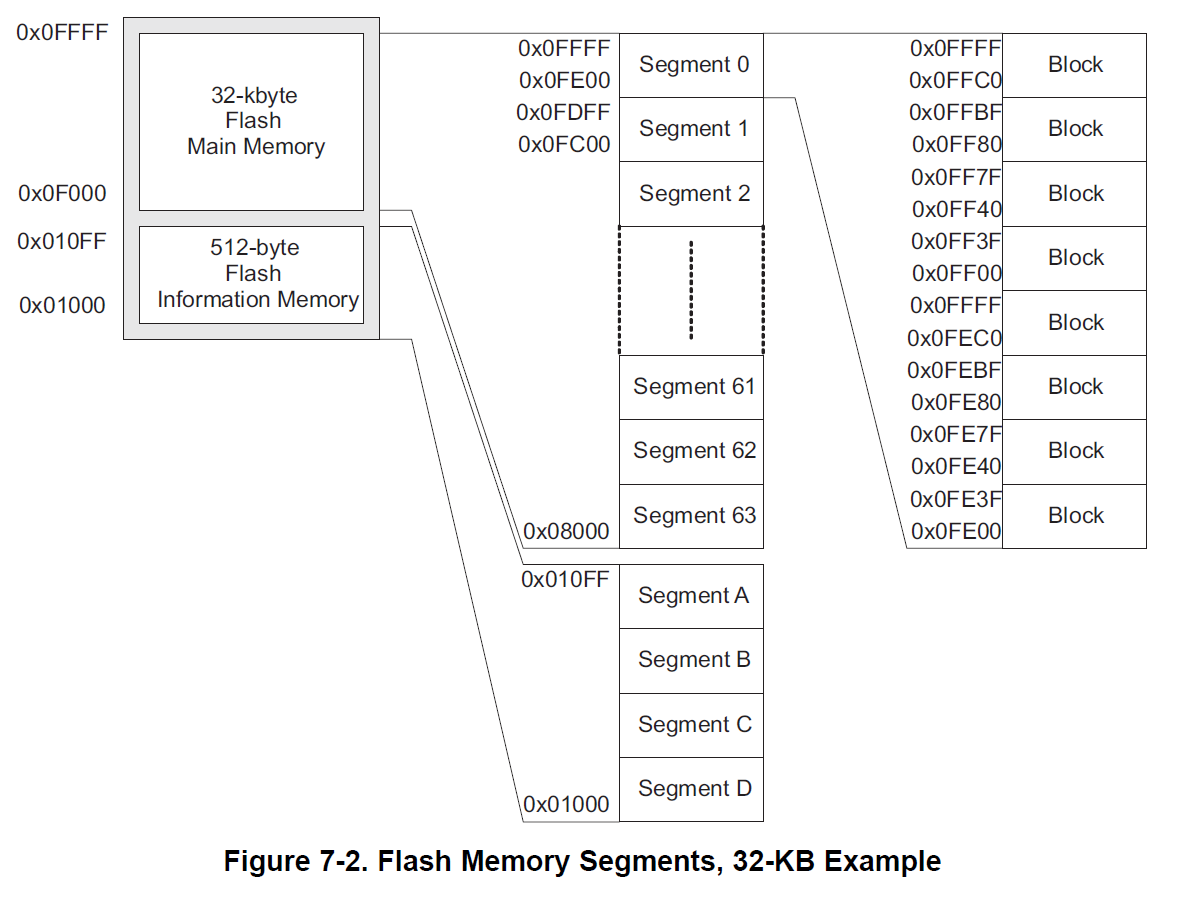
- Unterteilung des MSP430-Flash in verschiedene Segmente
- Eine ERASE-Operation löscht ein Segment vollständig. D. h. alle Speicherzellen werden auf den Wert
0xffgesetzt. - Segment A-D: jeweils 64 Bytes groß
- Segment A enthält Kalibrierungsdaten und sollte nicht gelöscht werden:
- Zusätzliches LOCKA-Bit zum Entsperren des Segmentes A
- Kalibrierungsdaten:
CALBC1_1MHZ,CALDCO_1MHZfür die Kalibrierung des Basic Clock Module für 1, 8, 12 oder 16 MHz- Kalibrierung des ADC (Offset, Gain)
- Kalibrierung des Temperaturssensors
- Kalibrierung des Referenzspannungsquellen des ADC
- Segmente B-D stehen zur freien Verfügung
- Segmente 0 - 63 enthalten jeweils 512 Bytes (64 · 512 = 32 KB)
- C-Compiler speichert das Programm ab
0x8000
Speicherauflistung des Projektes siehe Projektpfad/Debug/ProjectName.map
SECTION ALLOCATION MAP

output                                  attributes/
section   page    origin      length       input sections
--------  ----  ----------  ----------   ----------------
.stack     0    000005b0    00000050     UNINITIALIZED
                000005b0    00000002     rts430_eabi.lib : boot.c.obj (.stack)
                000005b2    0000004e     --HOLE--

.text      0    00008000    000000be
                00008000    00000046     main.obj (.text:main)
                00008046    00000022     main.obj (.text:flash_write)
                00008068    0000001e     main.obj (.text:flash_erase)
                00008086    00000014     rts430_eabi.lib : boot.c.obj (.text:_c_int00_noinit_noargs)
                0000809a    00000012     main.obj (.text:PORT2_ISR)
                000080ac    00000008     rts430_eabi.lib : isr_trap.asm.obj (.text:_isr:__TI_ISR_TRAP)
                000080b4    00000006                     : exit.c.obj (.text:abort)
                000080ba    00000004                     : pre_init.c.obj (.text:_system_pre_init)
- Segment 0 enthält den Interrupt-Vector und darf auf keinen Fall überschrieben werden
Programmierung
- Zugriff auf eine Speicherzelle in C mit Hilfe von Zeigern:
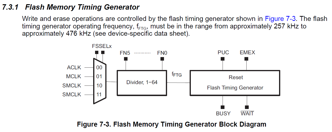
Einstellen des Taktgebers für den FMC (8_2a_flash)
ERASE-Operation (8_2a_flash)
void flash_erase(uint8_t *address) {
  FCTL3 = FWKEY;           // Clear Lock bit
  FCTL1 = FWKEY + ERASE;   // Set Erase bit
  *address = 0;          // Dummy write
  FCTL1 = FWKEY;           // Clear Erase bit
  FCTL3 = FWKEY + LOCK;    // Set LOCK bit
}
→ Das gesamte Segment, in dem sich
address befindet, wird gelöscht
WRITE-OPERATION (8_2a_flash)
void flash_write(uint8_t *address, uint8_t value) {
  FCTL3 = FWKEY;        // Clear Lock bit
  FCTL1 = FWKEY + WRT;  // Set WRT bit for write operation
  *address = value;     // Write
  FCTL1 = FWKEY;          // Clear WRT bit
  FCTL3 = FWKEY + LOCK;     // Set LOCK bit
}
Hochzählen des Wertes im Flash-Speicher (8_2a_flash)
uint8_t new_value = *data_pointer + 1;
flash_erase(data_pointer);
flash_write(data_pointer, new_value);
!!! ACHTUNG: Andere Werte in Segment D gehen verloren!
Gesamtes Programm
#include <msp430.h>
#include <stdint.h>

void update_led();
void flash_init();
void flash_erase(uint8_t *address);
void flash_write(uint8_t *address, uint8_t value);

static uint8_t *data_pointer = (uint8_t *) 0x1000;

int main(void) {
    WDTCTL = WDTPW | WDTHOLD;   // stop watchdog timer

    BCSCTL1 = CALBC1_1MHZ;
    DCOCTL = CALDCO_1MHZ;

    // RGB LED
    P2OUT &= ~(BIT1 + BIT3 + BIT5);
    P2DIR |= BIT1 + BIT3 + BIT5;
    update_led();

    // Button
    P1DIR &= ~BIT3;
    P1OUT |= BIT3;
    P1REN |= BIT3;
    P1IES |= BIT3;
    P1IFG &= ~BIT3;
    P1IE |= BIT3;

    flash_init();

    __enable_interrupt();

    while (1) {
        __low_power_mode_3();

        uint8_t new_value = *data_pointer + 1;
        if (new_value >= 6) {
            new_value = 0;
        }

        flash_erase(data_pointer);
        flash_write(data_pointer, new_value);
        update_led();
    }
}

void update_led() {
    switch (*data_pointer) {
    case 0:
        P2OUT |= BIT1;
        P2OUT &= ~(BIT3 + BIT5);
        break;
    case 1:
        P2OUT |= BIT1 + BIT3;
        P2OUT &= ~ BIT5;
        break;
    case 2:
        P2OUT |= BIT3;
        P2OUT &= ~(BIT1 + BIT5);
        break;
    case 3:
        P2OUT |= BIT3 + BIT5;
        P2OUT &= ~BIT1;
        break;
    case 4:
        P2OUT |= BIT5;
        P2OUT &= ~(BIT1 + BIT3);
    case 5:
        P2OUT |= BIT1 + BIT5;
        P2OUT &= ~BIT3;
        break;
    }
}

void flash_init() {
    FCTL2 = FWKEY + FSSEL_1 + FN1;  // SMCLK / 3 -> 333 kHz
}

void flash_erase(uint8_t *address) {
    FCTL3 = FWKEY;           // Clear Lock bit
    FCTL1 = FWKEY + ERASE;   // Set Erase bit
    *address = 0;            // Dummy write
    FCTL1 = FWKEY;           // Clear Erase bit
    FCTL3 = FWKEY + LOCK;    // Set LOCK bit
}

void flash_write(uint8_t *address, uint8_t value) {
    FCTL3 = FWKEY;          // Clear Lock bit
    FCTL1 = FWKEY + WRT;    // Set WRT bit for write operation
    *address = value;       // Write
    FCTL1 = FWKEY;          // Clear WRT bit
    FCTL3 = FWKEY + LOCK;   // Set LOCK bit
}

#pragma vector=PORT1_VECTOR
__interrupt void PORT1_ISR() {
    if (P1IFG & BIT3) {
        P1IFG &= ~BIT3;
        __low_power_mode_off_on_exit();
    }
}