6502 - Reaktion auf Eingangssignalen
Überblick
- Der Zustand der Tastern kann über den VIA 6522 überwacht werden.
DDRx = 0setzt den entsprechenden Pin als Eingang.- Durch Lesen des IRx-Registers (gleiche Adresse, wie ORx) kann der Zustand abgefragt werden.
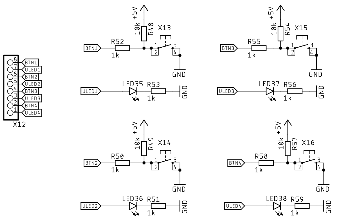
| PA0 | PA1 | PA2 | PA3 | PA4 | PA5 | PA6 | PA7 |
|---|---|---|---|---|---|---|---|
| BTN1 | D1 | BTN2 | D2 | BTN3 | D3 | BTN4 | D4 |
Lesen des Eingangs-Registers
Erstes Beispiel
Lesen des Registers IRA und Setzen des Wertes in ORB
reset:
    ldx #$ff
    txs

    lda #(LED1 + LED2 + LED3 + LED4)
    sta DDRA
    lda #0xFF
    sta DDRB

loop:
    lda ORA
    sta ORB

    jmp loop
Resultierende Bus-Aktivität
> AB = 0x800F  R  DB = 0xAD          lda $7f01
> AB = 0x8010  R  DB = 0x01
> AB = 0x8011  R  DB = 0x7F
> AB = 0x7F01  R  DB = 0x55
> AB = 0x8012  R  DB = 0x8D          sta $7f00
> AB = 0x8013  R  DB = 0x00
> AB = 0x8014  R  DB = 0x7F
> AB = 0x7F00  w  DB = 0x55
> AB = 0x8015  R  DB = 0x4C          jmp $800f
> AB = 0x8016  R  DB = 0x0F
> AB = 0x8017  R  DB = 0x80
Bitmanipulation
- Ziel: Wird ein Taster gedrückt, so soll die zugehörige LED leuchten.
Bitmanipulation der Taster und LED1
loop:
    lda ORA
    and #BTN1

    bne ledoff

    lda ORA
    ora #LED1
    sta ORA
    jmp loop

ledoff:
    lda ORA
    and #~LED1
    sta ORA

    jmp loop
Erweitertes Beispiel für alle LEDs mit Subroutine und Listenzugriff
ldx #0
loop:
    jsr led_btn_update
    inx
    txa
    and #3
    tax
    jmp loop

led_btn_update:
    lda ORA
    and BTNS,x
    bne ledoff
    lda ORA
    ora LEDS,x
    sta ORA
    rts
ledoff:
    lda #0xFF
    eor LEDS,x
    and ORA
    sta ORA
    rts

BTNS:
    .byte BTN1
    .byte BTN2
    .byte BTN3
    .byte BTN4
LEDS:
    .byte LED1
    .byte LED2
    .byte LED3
    .byte LED4
Interrupts
Überblick
- Der 6502 unterstützt zwei verschiedene Interrupts
- NMI (non-maskable interrupt)
- IRQ (interrupt request)
- Zu jeden dieser Interrupts gibt es ein zugehörigen Pin, wird dieser auf Masse gezogen, so kann der Interrupt ausgelöst werden.
Testprogramm für NMI und IRQ
    .org 0x8000
reset:
    ; cli
    ldx #$ff
    txs
    lda #0xFF
    sta DDRB

    lda #0
loop:
    sta ORB
    jmp loop

nmi:
    inc a
    rti

irq:
    dec a
    rti

    .org $FFFA
    .word nmi
    .word reset
    .word irq
NMI
- Der NMI kann nicht unterbunden werden.
- Bei einem H→L-Übergang am NMIB-Pin wird der NMI aktiv.
- Die Adresse der Interrupt-Service-Routine (ISR) wird in den Speicherzellen 0xFFFA und 0xFFFB abgelegt.
- Zuvor müssen die Rückkehradresse (PCL und PCH) und den der Prozessorstatus in im Stapel abgelegt werden.
- Die ISR wird durch die RTI-Anweisung (return from interrupt) verfassen.
- PC und Status-Register werden wiederhergestellt.
Bus-Aktivität während eines NMI
> AB = 0x800A  R  DB = 0x8D          sta $7f00
> AB = 0x800B  R  DB = 0x00    NMIB
> AB = 0x800C  R  DB = 0x7F
> AB = 0x7F00  w  DB = 0x17
> AB = 0x800D  R  DB = 0x4C          jmp $800a
> AB = 0x800D  R  DB = 0x4C
> AB = 0x01FF  w  DB = 0x80
> AB = 0x01FE  w  DB = 0x0D
> AB = 0x01FD  w  DB = 0x67
> AB = 0xFFFA  R  DB = 0x10
> AB = 0xFFFB  R  DB = 0x80
> AB = 0x8010  R  DB = 0x1A          ina A
> AB = 0x8011  R  DB = 0x40
> AB = 0x8011  R  DB = 0x40          rti
> AB = 0x8012  R  DB = 0x3A
> AB = 0x01FC  R  DB = 0x80
> AB = 0x01FD  R  DB = 0x67
> AB = 0x01FE  R  DB = 0x0D
> AB = 0x01FF  R  DB = 0x80
> AB = 0x800D  R  DB = 0x4C          jmp $800a
> AB = 0x800E  R  DB = 0x0A
IRQ
- Der IRQ-Interrupt muss durch das entsprechenden Wert im Prozessor-Status aktiviert werden.
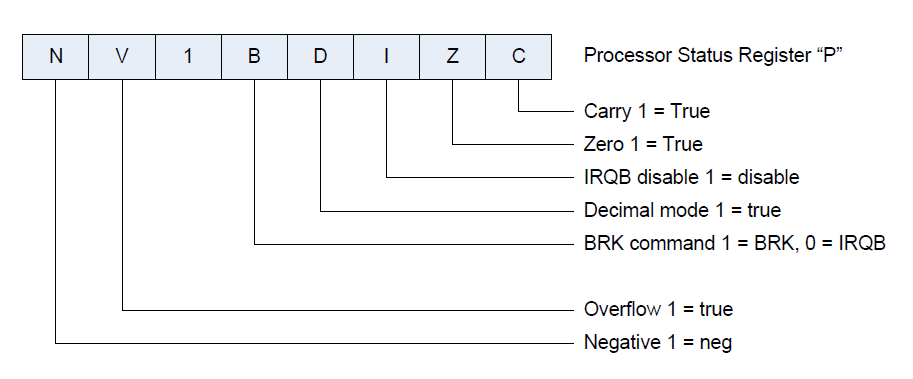
- Es wird solange die zugehörige ISR ausgeführt, wie IRQB auf L-Pegel ist.
- Der zugehörige Interrupt-Vektor befindet sich in den Speicherzellen 0xFFFE, 0xFFFF
Bus-Aktivität während eines IRQ
> AB = 0x800E  R  DB = 0x4C          jmp $800b
> AB = 0x800F  R  DB = 0x0B
> AB = 0x8010  R  DB = 0x80    IRQB
> AB = 0x800B  R  DB = 0x8D    IRQB  sta $7f00
> AB = 0x800B  R  DB = 0x8D    IRQB
> AB = 0x01FF  w  DB = 0x80
> AB = 0x01FE  w  DB = 0x0B
> AB = 0x01FD  w  DB = 0x63
> AB = 0xFFFE  R  DB = 0x13
> AB = 0xFFFF  R  DB = 0x80
> AB = 0x8013  R  DB = 0x3A          dea A
> AB = 0x8014  R  DB = 0x40
> AB = 0x8014  R  DB = 0x40          rti
> AB = 0x8015  R  DB = 0x00
> AB = 0x01FC  R  DB = 0x80
> AB = 0x01FD  R  DB = 0x63
> AB = 0x01FE  R  DB = 0x0B
> AB = 0x01FF  R  DB = 0x80
> AB = 0x800B  R  DB = 0x8D          sta $7f00
Pin-Interrupts durch den 6522
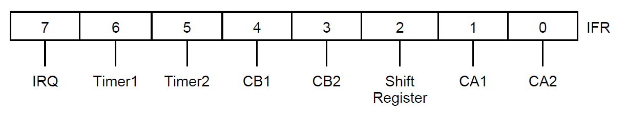
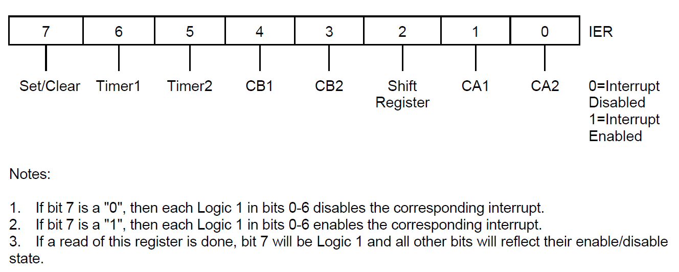
- Der 6522 kann aus 7 verschiedenen Quellen einen Interrupt erzeugen und gibt diesen durch das Setzen der IRQB-Leitung an den 6502.
- Hierfür wird das IFR (Interrupt Flag Register) (0x0D) und das IER (Interrupt Enable Register) (0x0E) benötigt.
- Die vier Taster sind mit den vier Interrupt-Pins des 6522 verbunden
| Taster | Port A | Interrupt |
|---|---|---|
| BTN1 | PA0 | CA1 |
| BTN2 | PA2 | CA2 |
| BTN3 | PA4 | CB1 |
| BTN4 | PA6 | CB2 |
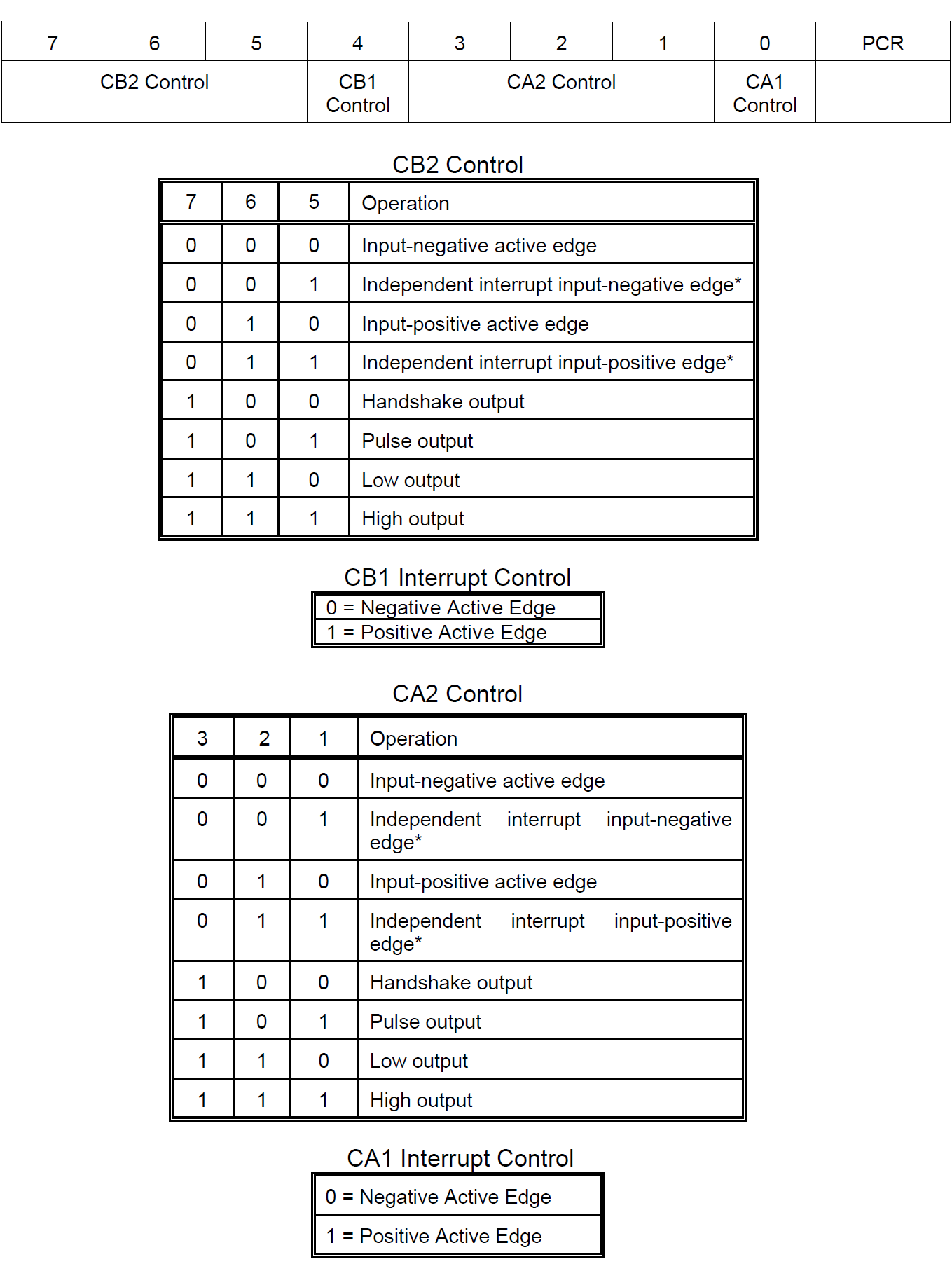
- Im PCR (Peripheral Control Register) (0x0C) wird die Interrupt-Flanke eingestellt.
Pin-Interrupts durch Taster 1
ORB = 0x7F00
ORA = 0x7F01
DDRB = 0x7F02
DDRA = 0x7F03
PCR = 0x7F0C
IFR = 0x7F0D
IER = 0x7F0E

CA1 = 0x02
CA2 = 0x01
CB1 = 0x10
CB2 = 0x08

    .org 0x8000
reset:
    cli
    ldx #$ff
    txs

    lda #0xFF
    sta DDRB

    lda #0
    sta PCR
    sta IFR

    lda #0x82
    sta IER

    lda #0
    sta ORB
loop:
    jmp loop

irq:
    lda IFR
    and #CA1
    beq exit_irq
    inc ORB
    bit ORA
exit_irq:
    rti

    .org $FFFA
    .word reset
    .word reset
    .word irq