Serial Interfaces - UART
Overview
- UART = Universal Asynchronous Receiver Transmitter
- Sending and Receiving via one data line each (TXD, RXD)
- Origin: RS-232 Standard has additional control lines
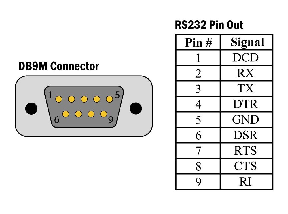
- Communication on the TXD and RXD line via voltage signals.

- Voltage level dependent on the microcontroller's logic level: MSP430 → 3.3 V
- When interfacing with other microcontroller the voltage level needs to be matched: keyword level-shifter.

- Signal level of an unused signal line is H.
- The transmission is done bytewise.
- Transmission starts with an Start-Bit - always low level.
- Bits of transmission Byte are send. Signal level is dependent on the bit's value.
- A minimum of one stop bit is added on the end of each byte - always high level.
- The bit-width Tb is dependent on the transmission rate.
- Transmission rate is also called baud rate. Because of the typical unit: 1 Baud = 1 bit/s.
- Baud rate settings of transmitted and receiver must match and have to be set before the communication.
- Typical baud rates: 2400, 4800, 9600, 115200 Baud
Setting up a UART connection on the MSP430
MSP430 Registers
Step-by-Step Instruction
Calibrating the DCO
- see Task 4.4
- The SMCLK clock frequency is on startup around 1 MHz.
- Because timing is very important to send and decode UART signals, an additional clock calibration is needed.
- Calibration data for the DCO is stored in flash storage of the MSP430.
- DCO calibration data for 1, 8, 12 and 16 MHz is available.
- To load the calibration values, the following two commands need to be added after the watchdog timer halt.
Selecting the Pins
- The pins P1.1 and P1.2 must be used on the MSP430G2553 for UART output.
- see pinout of the MSP430G2553
- the PxSEL and PxSEL2 bits have to be set, to connect the communication module of the MSP430 to these pins.
USCI Software Reset
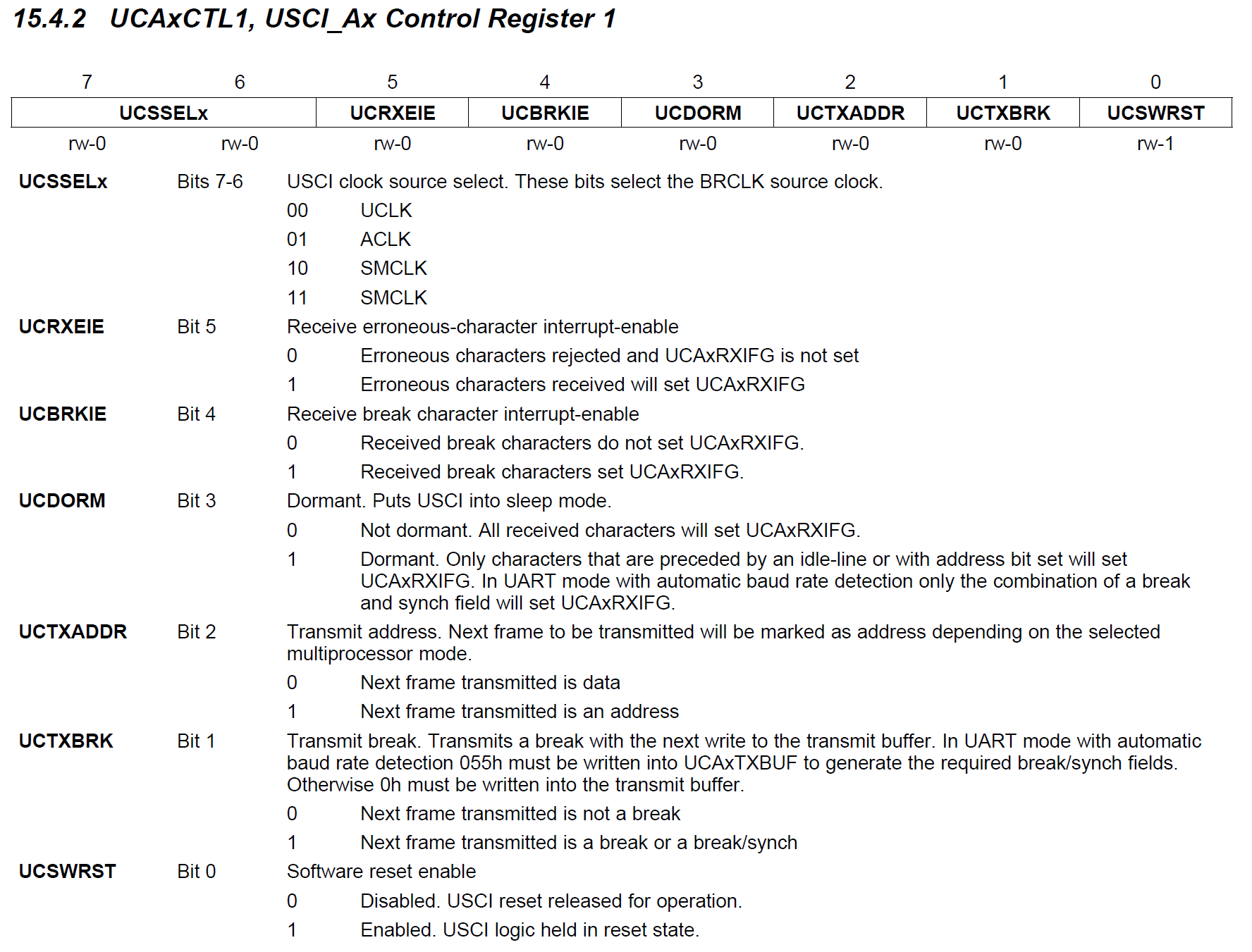
- The software reset bit UCSWRST is located in the UCA0CTL1 register.
- While the configuration of the USCI module is changed this bit must be set.
- After the configuration the bit is released and the module starts working.
Setting the USCIA configuration
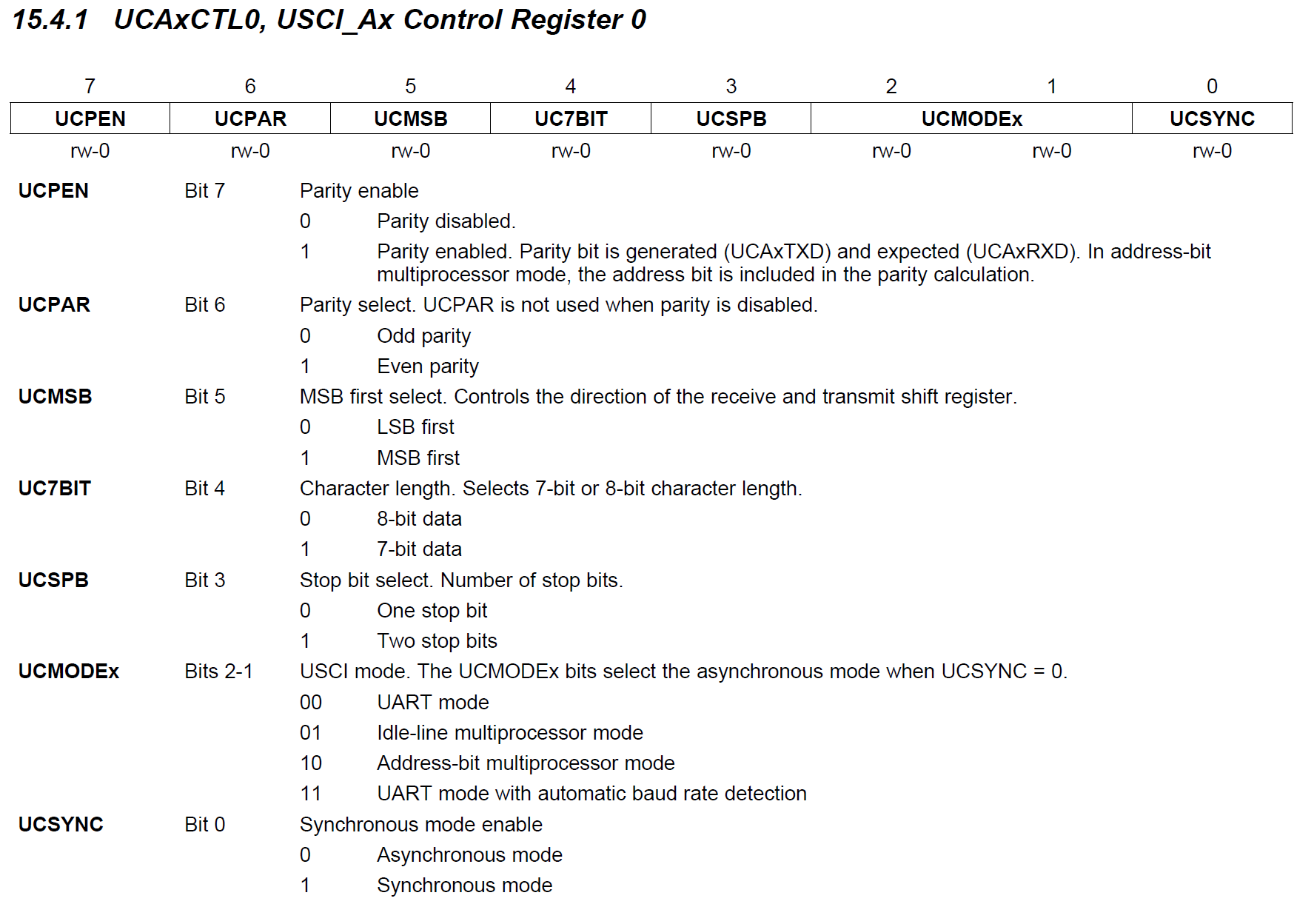
- As you can see in UCA0-register description a normal UART communication is the default:
- no parity check
- LSB first
- 8-bit data
- one stop bit
- UART mode
- Asynchronous mode (no clock signal)
- In the UCA0CTL1 register only the clock source needs to be set.
- The SMCLK with an clock frequency of 1 MHz will be used.
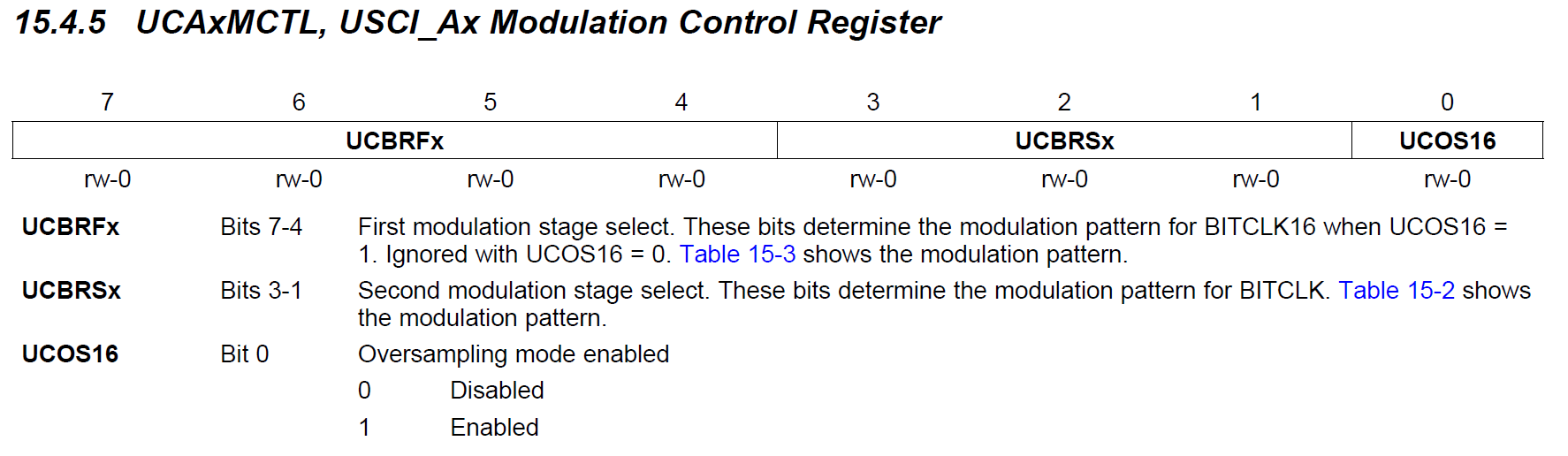
Setting the Baud Rate
- The baud rate setting is rather complex at the MSP430. Several tricks are used to generate a precise UART signal.
- More complex is also the signal reception. The signal is sampled multiple times per bit. A majority vote decides on the bits value.
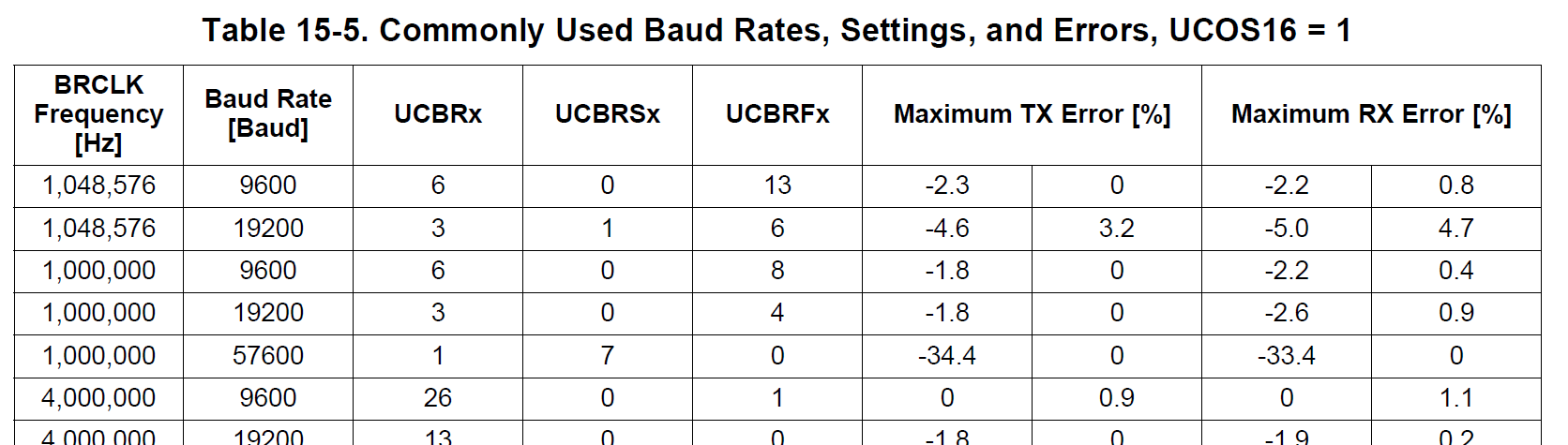
- That is why the table seen previously is needed to set the timing registers.
- If we want to generate a 9600 Baud signal at 1 MHz the following values can be read from the table.
- The following registers need to be set.
UCA0BR0andUCA0BR1.
withUSCBRx = UCA0BR0 + 256 * UCA0BR1UCA0MCTL = (UCBRFx << 4) + (UCBRSx << 1) + UCOS16
Sending a UART character
- UART messages can be send bytewise.
- To send a message the
UCA0TXBUFneeds to be set. - One needs to ensure, that this register is never set faster than the USCIA can send the data.
- In our example program we want to send the character 'x', when the button on pin P1.3 was pressed.
- Use the following ISR for PORT1
#pragma vector=PORT1_VECTOR
__interrupt void PORT1_ISR() {
if (P1IFG & BIT3) {
P1IFG &= ~BIT3;
UCA0TXBUF = 'x';
}
}
Receiving a UART character
- To receive a character over UART an interrupt is used.
- To enable the interrupt the following bit needs to be set.
- The following ISR was used to decode the message.
- The corresponding interrupt flag UCA0RXIFG is located inside the IFG2.
- The received character can be read from the UCA0RXBUF.
- The LEDs of the RGB LED are toggled when the corresponding character r, g, or b is received.
#pragma vector=USCIAB0RX_VECTOR
__interrupt void USCI0RX_ISR(void) {
if (IFG2 & UCA0RXIFG) {
IFG2 &= ~UCA0RXIFG;
char received_char = UCA0RXBUF;
switch (received_char) {
case 'r':
P2OUT ^= BIT1;
break;
case 'g':
P2OUT ^= BIT3;
break;
case 'b':
P2OUT ^= BIT5;
break;
default:
break;
}
}
}
Low-Power-Mode
- The LPM 4 can be used in this program.
- The SMCLK is used while sending and receiving of bytes - this clock is disabled in LPM4.
- But the MSP430 automatically enables the SMLCK when the sending or reception of a signal is started. The clock is disabled afterwards.
Question
Built the program described in the following sections. Don't forget to set the pin configuration of the button and the RGB LEDs.
Summary:
- A 'x' should be sent from the MSP430, when button P1.3 gets pressed.
- When a 'r' is received the red LED of the RGB LED should be toggled.
- When a 'g' is received the green LED and when a 'b' is received the blue LED.
Solution
#include <msp430.h>
#include <stdint.h>
int main(void) {
WDTCTL = WDTPW | WDTHOLD; // stop watchdog timer
BCSCTL1 = CALBC1_1MHZ;
DCOCTL = CALDCO_1MHZ;
P2OUT &= ~(BIT1 + BIT3 + BIT5);
P2DIR |= BIT1 + BIT3 + BIT5;
P1DIR &= ~BIT3;
P1OUT |= BIT3;
P1REN |= BIT3;
P1IES |= BIT3;
P1IFG &= ~BIT3;
P1IE |= BIT3;
P1SEL |= BIT1 + BIT2;
P1SEL2 |= BIT1 + BIT2;
UCA0CTL1 |= UCSWRST;
UCA0CTL0 = 0;
UCA0CTL1 |= UCSSEL_2;
UCA0BR0 = 6;
UCA0BR1 = 0;
UCA0MCTL = (8 << 4) + UCOS16;
UCA0CTL1 &= ~UCSWRST;
UC0IE |= UCA0RXIE;
__enable_interrupt();
while (1) {
__low_power_mode_4();
}
}
#pragma vector=USCIAB0RX_VECTOR
__interrupt void USCI0RX_ISR(void) {
if (IFG2 & UCA0RXIFG) {
IFG2 &= ~UCA0RXIFG;
char received_char = UCA0RXBUF;
switch (received_char) {
case 'r':
P2OUT ^= BIT1;
break;
case 'g':
P2OUT ^= BIT3;
break;
case 'b':
P2OUT ^= BIT5;
break;
default:
break;
}
}
}
#pragma vector=PORT1_VECTOR
__interrupt void PORT1_ISR() {
    if (P1IFG & BIT3) {
        P1IFG &= ~BIT3;
        UCA0TXBUF = 'x';
    }
}
Testing the program
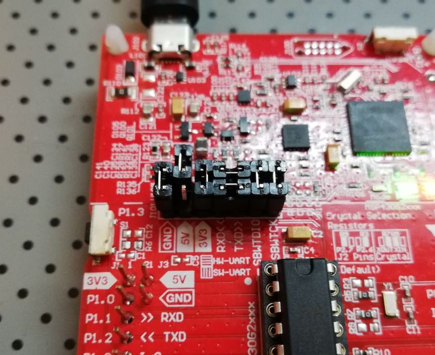
- No additional microcontroller is used to communicated with.
- A PC can be used to receive UART signals. A UART-USB converter can be used.
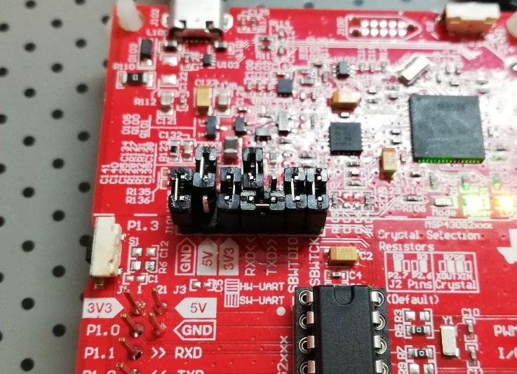
- Such a converter is built in the Launchpad.
- Make sure to connect the RXD and TXD lines of the launchpad correctly. The corresponding jumpers need to be set perpendicularly.
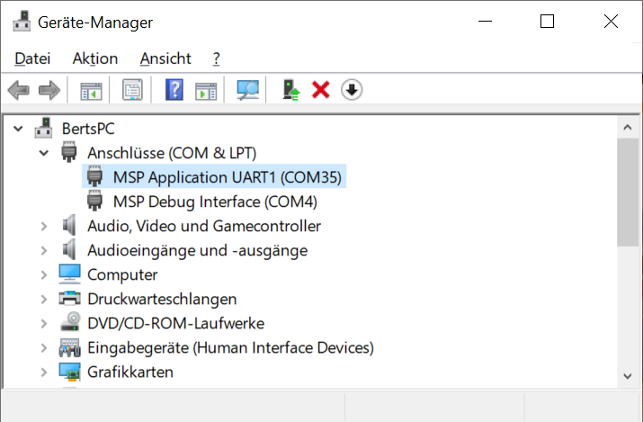
- Finding out the COM port:
- In the windows device manager two COM ports are added, when the Launchpad is connected.
- Use the COM port marked with MSP Application UART1.
- To connect to the COM port, multiple programs can be used.
- PuTTY, see https://www.putty.org/
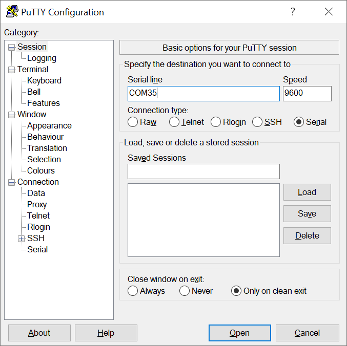
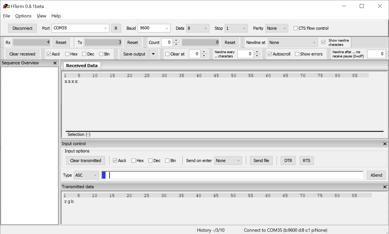
- PuTTY is recommended when using long ASCII messages - later when the testing environment is introduced.
- HTerm is recommend when using single characters. Converting in HEX or DEC can be enabled.
Debug Terminal
Example
- The debug terminal is the first module used in our wake-up receiver firmware.
- The idea is to implement a very easy but lightweight way to send debug messages and observe the program in runtime.
- The UART protocol is used to send messages from the MSP430 to an console on the PC.
- The reverse data direction - sending messages from the PC to the MSP430 is not used. This way P1.1 can be used for other purposes. The corresponding jumper on the launchpad should be left open, otherwise the UART-USB converter will interfere with the connection circuitry on this pin.
- Download of the source files: term_modified.zip
- Add these files to your project.
- Take a look at the source files of the debug terminal.
- All function are grayed out, because the symbol
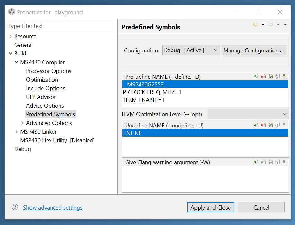
TERM_ENABLEis not defined. - Defining
TERM_ENABLEin build options:- Right click on project in Project Explorer
- Properties
- Build → Predefined Symbols
- Add new Pre-define NAME:
TERM_ENABLE=1 - The clock frequency of the MSP430 must to be defined for the debug terminal.
- Add
P_CLOCK_FREQ_MHZ=1, too
Info
Functions of debug terminal
| Function | Parameters | Description |
|---|---|---|
| term_init | no | Initializing UCA0 module for UART use. |
| term_putchar | char c | Send character over UART. |
| term_print | char *str | Send a string over UART. End of string is defined by null-character '\0'. |
| term_log_begin | no | Function to start a logging message. |
| term_log_end | no | Function to end a logging message. |
| term_log | char *str | Sending a complete logging message. |
| term_uint | uint32_t number, uint8_t digit_count | Sending a unsigned number over UART. Function needs a static number of digits. |
| term_decimal | uint32_t number, uint8_t digit_count, uint8_t decimals | Sending a fixed decimal number over UART. |
| term_int | int32_t number, uint8_t digit_count | Sending a signed number over UART. |
| term_signed_decimal | int32_t number, uint8_t digit_count, uint8_t decimals | Sending a signed fixed decimal number over UART. |
| term_binary | uint16_t number, uint8_t digit_count | Sending a number in its binary form. Function needs a static number of digits. |
| term_hex | uint32_t number, uint8_t digit_count | Sending a number in its hexadecimal form. Function needs a static number of digits. |
| term_test_result | uint8_t result | Sending the result of a boolean test. If result is true a green P is printed, else a red X. |
| term_wait_and_clear | no | Wait 1 sec on startup and send 10 new lines over UART. |
Test program of debug terminal
#include <msp430.h>
#include <stdint.h>

#include "term.h"

int main(void) {
    WDTCTL = WDTPW | WDTHOLD;    // stop watchdog timer

    BCSCTL1 = CALBC1_1MHZ;
    DCOCTL = CALDCO_1MHZ;

    P1DIR &= ~BIT3;
    P1OUT |= BIT3;
    P1REN |= BIT3;
    P1IES |= BIT3;
    P1IFG &= ~BIT3;
    P1IE |= BIT3;

    P1SEL |= BIT2;
    P1SEL2 |= BIT2;

    term_init();
    term_wait_and_clear();
    term_log("Program initialized!");

    __enable_interrupt();

    while (1) {
        __low_power_mode_4();
        term_log("Button pressed.");
    }
}

#pragma vector=PORT1_VECTOR
__interrupt void PORT1_ISR() {
    if (P1IFG & BIT3) {
        P1IFG &= ~BIT3;
        __low_power_mode_off_on_exit();
    }
}
Question
Try out some other function of the terminal module. Write a program that counts up a number, each time the button gets pressed. Display this number using the function term_uint(), term_int(), term_binary() or term_hex().
Debug Terminal in Wake-up Receiver API
- The debug terminal is a very useful tool to debug the WuRx-API.
- On startup tests are run to ensure the corresponding hardware (wireless transceiver, WuRx, sensor, ...) correspond as expected.
- During program execution additional debug messages are printed.
- Problem: USCIA is used for SPI, wireless transceiver and WuRx are connected
- Solution: Switch to UART mode for output of debug messages, switch back after that
- Consequences:
term_log_begin()andterm_end()must be called at the beginning and end of every debug message- Debug messages during an SPI interaction are not allowed
- Some corrupted characters appear on UART terminal, due to SPI interactions
- Note that debug messages delay the program flow.
- e.g. transmission of 10 character: 10 · 8 bit / 9600 baud = 8.33 ms
- With wireless sensor networks multiple microcontroller boards must be programmed.
- Selecting the corresponding board in Code Composer Studio is not easy.
- Hint: Only connect the board you want to program.
- Connecting and disconnecting the closes the PuTTY window every time.
- So I wrote a small program to display the terminal output for every board connected to the PC.
- see https://github.com/RobFro96/UARTDebugger
- Installation process is shown on the Github page, use the command in the uart_debugger.bat to launch the terminal.
- All Launchpads are detected automatically!