Parallel Interface - Outputs
First Program
- With the help of outputs of the parallel interface for example LEDs can be switched on and off.
- On the Launchpad there are five LEDs, see the documentation of the Lauchpad
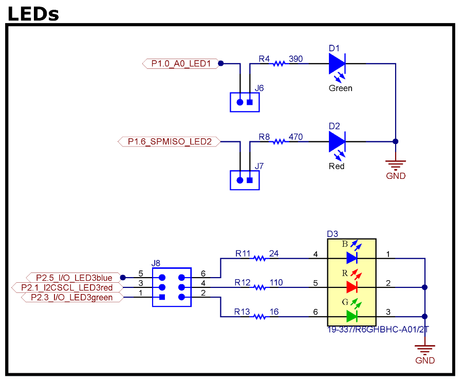
- In the first program the red and the green LEDs will blink. Make sure the jumper J6 and J7 are connected.
- The green LED is connected to pin P1.0, the red LED to P1.6
#include <msp430.h>

int main(void) {
    WDTCTL = WDTPW | WDTHOLD;  // stop watchdog timer

    P1DIR = 0xFF;
    __no_operation();

    while (1) {
        P1OUT = 0x41;
        __no_operation();
        P1OUT = 0x00;
        __no_operation();
    }
}
Line-per-line explanation of the program
#include <msp430.h>- Including the MSP430 header file
- Containing the definition of multiple MSP430 register constants, macros, ...
- e. g.
WDTCTL, WDTPW, P1DIR, P1OUT, BIT0, BIT1
int main(void) {- Head of a typical C main function
- Convention: main function returns an
int - Our main function returns nothing, because we use a endless loop
- Typical approach: microcontroller never end!
WDTCTL = WDTPW | WDTHOLD;- Disabling the so-called watchdog timer (WDT) of the MSP430
- This command is mandatory, otherwise WDT will stop the program immediately
- Do not forget to add this command as the first command of every program!
P1DIR = 0xFF;- P1DIR is the direction register of all 8 pins of port 1.
- According to the value of a single bit the corresponding pin is set to an input or output.
- The value 0xFF = 0b1111 1111 ensures, that all pins of port 1 are set to output.
__no_operation();
An additional no-operation command is added to enable a breakpoint after the execution of the previous register change. This command is not needed.while (1) {
Head of the endless loopP1OUT = 0x41;- The output register of port 1 P1OUT defines the values of the output pins.
- 0x41 = 0b0100 0001. The bits 0 and 6 are set.
- This results into Pin P1.0 and P1.6 been set H level → both LEDs turn on.
P1OUT = 0x00;- Resets all bits of the output register.
- Both LEDs turn off.
What happens inside the MSP430 when setting values to the port registers?

Question
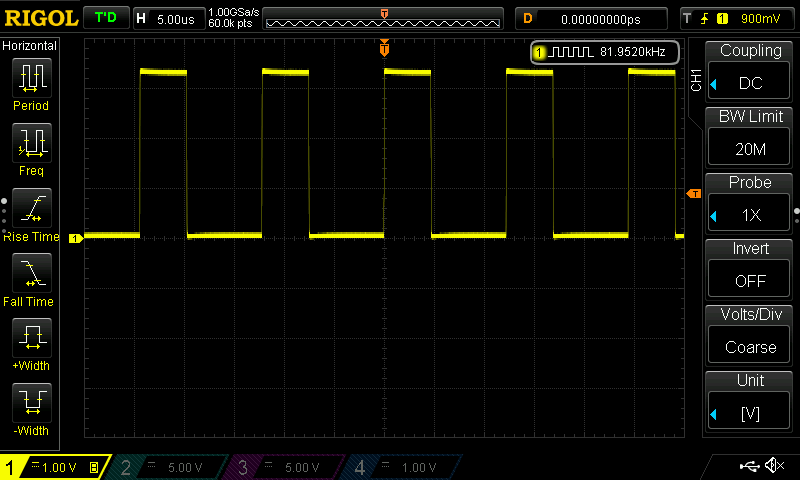
- What happens to the LEDs when the program runs freely?
- Probe the pins P1.0 and P1.6 of the MSP430 with an oscilloscope. Measure the frequency of the square wave.
- Why is the duty-cycle of the signal not 50%?
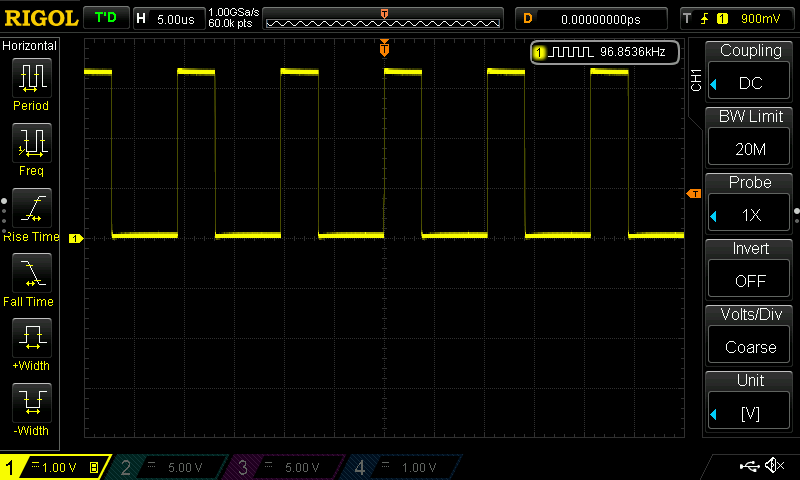
- Remove all
__no_operation()instructions and flash the MSP430 again. What are the changes in the signal? - The default clock frequency of the MSP430 is approx. 1 MHz. How many clock cycles does the MSP430 need to run one loop iteration? Per no-operation instruction only one clock cycle is needed.
Solution
Info
Debugging, Flashing and Compiling in Code Composer Studio
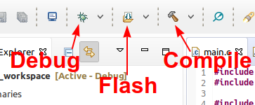
- If you want to debug your program:
- using breakpoint, single-step the program, watch register values, ...
- then program the MSP430 by clicking on the green bug symbol.
- If you want to program on the MSP430 without debugging - just let the new program run freely - then press the flash symbol, right to the debug symbol.
- If you want to verify your code, find out syntax error: click the compile symbol
Delaying the Program
Using a Loop
In order to see the LEDs blink the program need to be delayed by a software loops. Multiple possibilities are shown in the following programs.
#include <msp430.h>
#include <stdint.h>

int main(void) {
    WDTCTL = WDTPW | WDTHOLD;  // stop watchdog timer

    P1DIR = 0xFF;

    while (1) {
        P1OUT = 0x41;

        volatile uint16_t counter = 50000;
        while (counter > 0) {
            counter--;
        }

        P1OUT = 0x00;
        counter = 50000;
        while (counter > 0) {
            counter--;
        }
    }
}
C Data Types
- data types in C for integers:
char,short,int,long - prefix
unsignedmake variable unsigned, the value range can be doubled. - for ASCII character
charis used too. - native data types for boolean and character strings are not implemented.
- data type
intis typically one word wide. In case of the MSP430 16 bit, on a PC 32 bit. - More uniform is usage of the data types defined in the header file
stdint.h.
#include <stdint.h>
| stdint | native | size | minimum | maximum |
|---|---|---|---|---|
int8_t |
char |
8 bit | –128 | 127 |
uint8_t |
unsigned char or byte |
8 bit | 0 | 255 |
int16_t |
short (int) |
16 bit | –32 768 | 32 767 |
uint16_t |
unsigned short (unsigned int) |
16 bit | 0 | 65 535 |
int32_t |
long |
32 bit | –2 147 483 648 | 2 147 483 647 |
uint32_t |
unsigned long |
32 bit | 0 | 4 294 967 295 |
Volatile Variables and Compiler Optimization
- With the declaration of the variable
counterthe keywordvolatileis added. - This keyword ensures that the compiler does no optimization when working with the variable.
- Removing the keyword
volatileresults into the loops being optimized and removed. No delay is added. - Alternatively the complier optimization can be disabled in the compiler options.
Question
Use 10000 iterations as the delay. Ensure the doubled delay time is applied correctly.
Using a Function
#include <msp430.h>
#include <stdint.h>

void delay(uint16_t duration);

int main(void) {
    WDTCTL = WDTPW | WDTHOLD;  // stop watchdog timer

    P1DIR = 0xFF;

    while (1) {
        P1OUT = 0x41;
        delay(50000);
        P1OUT = 0x00;
        delay(50000);
    }
}

void delay(uint16_t duration) {
    volatile uint16_t counter = duration;
    while (counter > 0) {
        counter--;
    }
}
void delay(uint16_t duration);- This line is the prototype of the function.
- Every function needs an prototype so, that the C code can call this function.
- The prototype line is identical to function head, except a semicolon on the end.
void delay(uint16_t duration) {- This line is the head of the function.
- The return type is
void(nothing). - The function name is
delay. - The function need one parameter of type
uint16_tcalledduration.
- The function body is followed.
- Please use functions in your program, for ...
- ... structuring and organizing your program.
- ... summarize repeating tasks.
Using __delay_cycles()
__delay_cycles(n)is a built-in macro of themsp430.h.- The macro creates a delay of exactly
nclock cycles. nneeds to be an known value while compiling the program otherwise the will be a compile error.
#include <msp430.h>
#include <stdint.h>

int main(void) {
    WDTCTL = WDTPW | WDTHOLD;  // stop watchdog timer

    P1DIR = 0xFF;

    while (1) {
        P1OUT = 0x41;
        __delay_cycles(500000);
        P1OUT = 0x00;
        __delay_cycles(500000);
    }
}
Bit Manipulation
Info
Bit Manipulation
- Setting multiple bits in a variable:
variable |= bits; - Resetting multiple bits in a variable:
variable &= ~bits; - Toggling multiple bits in a variable:
variable ^= bits;
Bit Constants
The following bit constants are defined in the msp430.h.
| Constant | Bin | Hex | Dec |
|---|---|---|---|
| BIT0 | 0000 0001 | 0x01 | 1 |
| BIT1 | 0000 0010 | 0x02 | 2 |
| BIT2 | 0000 0100 | 0x04 | 4 |
| BIT3 | 0000 1000 | 0x08 | 8 |
| BIT4 | 0001 0000 | 0x10 | 16 |
| BIT5 | 0010 0000 | 0x20 | 32 |
| BIT6 | 0100 0000 | 0x40 | 64 |
| BIT7 | 1000 0000 | 0x80 | 127 |
Question
Whats the registers value after the execution of the command? Try to calculate the values by your own.
| Register's Value | Command | Result |
|---|---|---|
P1DIR = 0; |
P1DIR \|= 0b01000001; |
|
P1DIR = 0xF1; |
P1DIR \|= 0b01000001; |
|
P1OUT = 0xA5; |
P1OUT &=~ 0b00000001; |
|
P1OUT = 0xA5; |
P1OUT ^= 0b00001111; |
|
x = 0; |
x |= BIT0 + BIT6; |
|
y = 0x55; |
y &= ~(BIT0 + BIT2); |
|
P1OUT = 0x40; |
P1OUT ^= BIT0 + BIT6 |
Check your results by e.g. using the Python Online Shell: https://www.python.org/shell/. You can use the following command structure to see the results.
P1DIR = 0; P1DIR |= 0b01000001; print(hex(P1DIR) + " " + bin(P1DIR))
#include <msp430.h>
#include <stdint.h>

int main(void) {
    WDTCTL = WDTPW | WDTHOLD;  // stop watchdog timer

    P1DIR |= BIT0 + BIT6;
    P1OUT &= ~(BIT0 + BIT6);

    while (1) {
        P1OUT |= BIT0;
        P1OUT ^= BIT6;
        __delay_cycles(500000);
        P1OUT &= ~BIT0;
        P1OUT ^= BIT6;
        __delay_cycles(500000);
    }
}
P1DIR |= BIT0 + BIT6;Setting pins P1.0 and P1.6 to output.P1OUT &= ~(BIT0 + BIT6);Resetting both LED pins to GND.P1OUT |= BIT0;Set P1.0 to Vcc.P1OUT ^= BIT6;Toggle P1.6.P1OUT &= ~BIT0;Reset P1.0 to GND.
Question
The pins P2.1, P2.3 and P2.5 are connected to the RGB LED of the Launchpad (see pinout). Write a program that loop through the following colors:
- red
- yellow
- green
- cyan
- blue
- magenta
Solution
#include <msp430.h>
#include <stdint.h>

#define P_RED (BIT1)
#define P_GREEN (BIT3)
#define P_BLUE (BIT5)
#define DELAY (1000000)

int main(void) {
    WDTCTL = WDTPW | WDTHOLD;  // stop watchdog timer

    P2DIR |= BIT1 + BIT3 + BIT5;
    P2OUT &= ~(P_RED + P_GREEN + P_BLUE);

    // red
    P2OUT |= P_RED;

    while (1) {
        // red
        P2OUT &= ~P_BLUE;
        __delay_cycles(DELAY);

        // yellow
        P2OUT |= P_GREEN;
        __delay_cycles(DELAY);

        // green
        P2OUT &= ~P_RED;
        __delay_cycles(DELAY);

        // cyan
        P2OUT |= P_BLUE;
        __delay_cycles(DELAY);

        // blue
        P2OUT &= ~ P_GREEN;
        __delay_cycles(DELAY);

        // magenta
        P2OUT |= P_RED;
        __delay_cycles(DELAY);
    }
}