Serial Interfaces - SPI
Overview
- Serial Peripheral Interface
- synchronous serial data bus → additional clock line
- significantly faster transmissions possible compared to UART
- The clock signale is controlled by the master.
- 1 clock edge → Master sends 1 bit to slave, slave sends 1 bit to master
- after 8 clock edges 1 byte was exchanged between master ⇆ slave

- SPI signal lines:
- SCLK: serial clock
- MOSI: master out slave in
- MISO: master in slave out
- SS or CS: slave or chip select, active low

- Multiple SS Pins
- Each slave gets its own SS signal from the master.
- SS pins on the master are freely usable output pins.
- All SS pins are set to high, all slaves are deactivated.
- Only one SS pin is set to low, only one slave is selected.
- The communication over SPI works normally, deactivated slaves ignore the SPI signal.
SPI Slave Example: SPIRIT1
SPIRIT1
- The SPIRIT1 is a sub-Gigahertz wireless transceiver.
- Multiple register can be read and written to configure proper wireless data transmission and reception.
- In WuRx-API multiple modules are written to simplify the SPIRIT1 setup procedure.
- In this section only the reading of one register is shown as an example.
- Register 0xF0 contains information on part number and firmware version of the SPIRIT1.
Connections
- SPI is supported by the MSP430's USCIA and USCIB.
- The SPIRIT1 is connected to SPIA (see previous section).
- Summary of SPIRIT1 pinout
| SPIRIT1 | MSP430 |
|---|---|
| MISO | P1.1 |
| MOSI | P1.2 |
| SCK | P1.4 |
| IRQ | P2.0 |
| SPIRIT_CS | P2.1 (active low) |
| AS3933_CS | P2.5 (active high!) |
- The MOSI, MISO and SCK pins are fixed to MSP430's USCIA pins.
- For CS nearly every pin of the MSP430 can be used. This pin is used as a regular digital output to enable the CS on communication.
- Only one SPI slave can be active at a time → AS3933 must be disabled by AS3933_CS=L.
MSP430 Registers
Step-by-Step Instruction
Initialization
-
USCI Initialization:
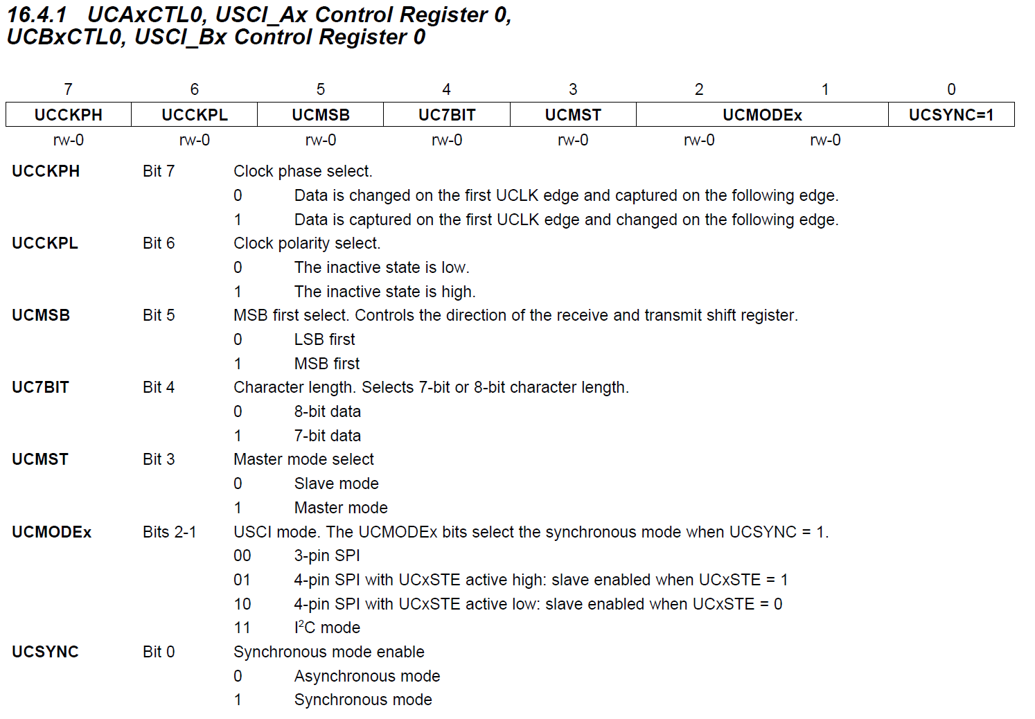
UCA0CTL1 |= UCSWRST; UCA0CTL0 = UCCKPH + UCMSB + UCMST + UCSYNC; // SPI phase, MSB first, master mode, synchronous UCA0BR0 = 1; UCA0BR1 = 0; UCA0CTL1 = UCSSEL_2;- Hold the reset bit while initialization.
- MSB first (
UCMSB) - MSP430 is master (
UCMST) - Setting Clock Phase and Clock Polarity
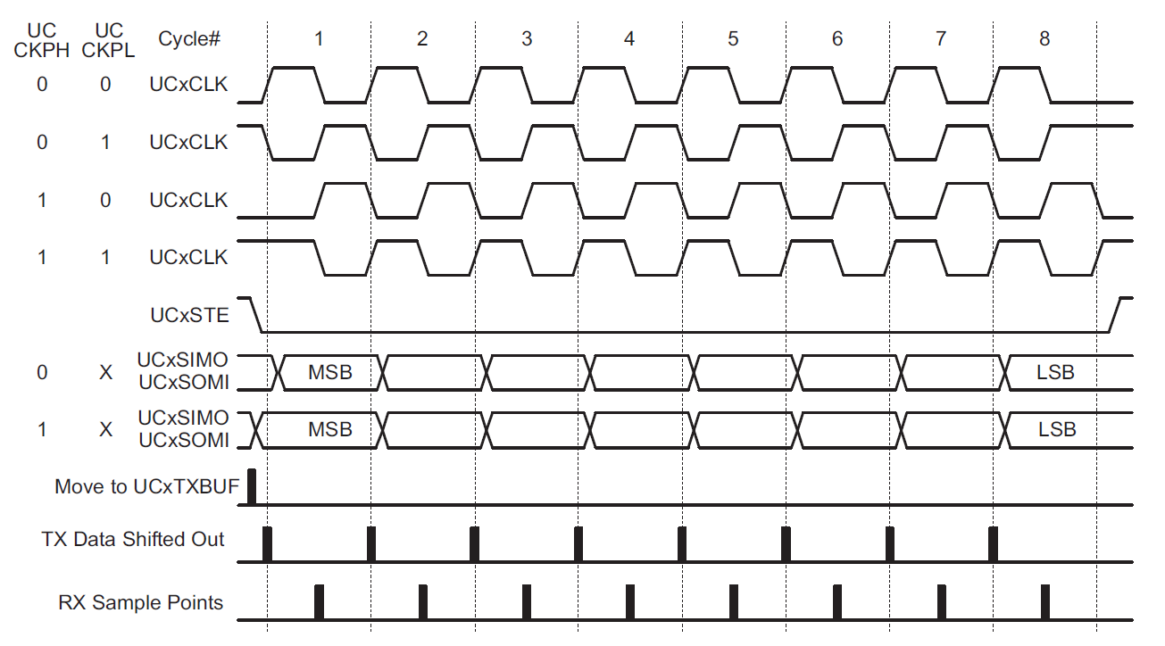
- Clock Phase and Polarity needs to be set according the device.
- The industry quasi standard is:
- Base value of SCLK is zero.
- Data are read on the clock's rising edge and data are changed on the clock's falling edge.
- Resulting in
UCCKPL=0andUCCKPH=1.
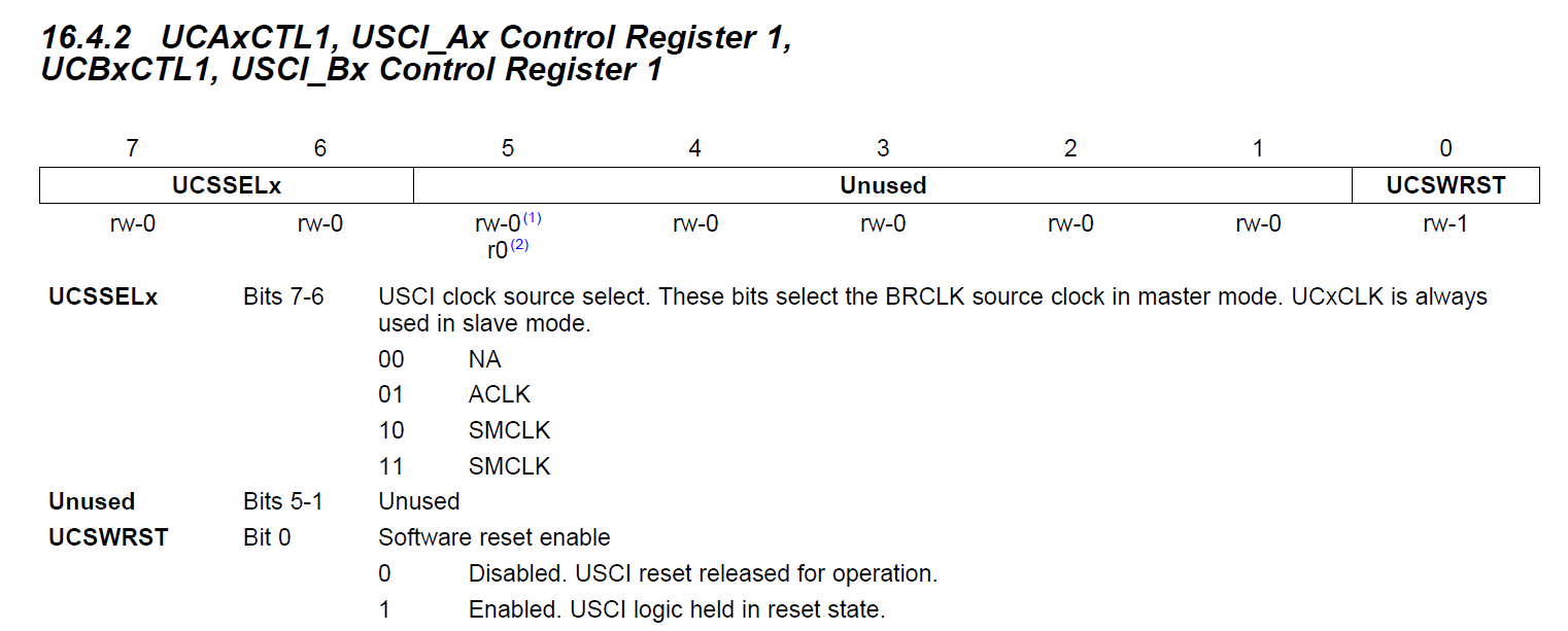
- The SMCLK is used as clock reference (
UCSSEL_2). -
The clock divider is set to 1.
\[ \text{Divider} = \text{UCB0BR0} + 256 \cdot \text{UCB0BR1} \]
- Resulting a SPI clock frequency of 1 MHz.
- The reset bit is released while writing to
UCB0CTL1 = UCSSEL_2.
Reading PARTNUM and VERSION
As an example we want to read the values PARTNUM and VERSION from register 0xF0:
- Enable the device by pulling the CS pin to L.
- The first byte that needs to be transferred has the value 0x01 (reading from a register, see datasheet p. 76).
-
Use the following flag polling loop to ensure, no communication is running.
-
When writing to the
UCA0TXBUFregister the transmission is started.
- Add another flag polling loop before sending the second byte. This byte is the register address 0xF0.
- After this SPI interaction the SPIRIT1 will send the data bytes.
- We need to send any byte over SPI, wait from transmission complete and store the received byte.
while (!(IFG2 & UCA0TXIFG)) {
}
UCA0TXBUF = 0x00;
while (!(IFG2 & UCA0TXIFG)) {
}
uint8_t partnum = UCA0RXBUF;
- The same is repeated with the second byte, containing the version number instead.
- Disable the device by pulling the CS pin to H.
Displaying the result
- No UART output can be used, so the LED will be lit up, when the received values are correct.
- The partnum=0x01 and version=0x30 corresponds the current SPIRIT1 devices.
- Light up the LED and wait before repeating the SPI interaction.
SPI Library Module and Debug Terminal
- The debug terminal is a very useful tool to debug the WuRx-API.
- On startup tests are run to ensure the corresponding hardware (wireless transceiver, WuRx, sensor, ...) correspond as expected.
- During program execution additional debug messages are printed.
Warning
Only for older versions of the WuRx hardware
- Problem: USCIA is used for SPI, wireless transceiver and WuRx are connected
- Solution: Switch to UART mode for output of debug messages, switch back after that
- Consequences:
term_log_begin()andterm_end()must be called at the beginning and end of every debug message- Debug messages during an SPI interaction are not allowed
- Some corrupted characters appear on UART terminal, due to SPI interactions
- Note that debug messages delay the program flow.
- e.g. transmission of 10 character: 10 · 8 bit / 9600 baud = 8.33 ms
Warning
For the Kokowei versions of the WuRx hardware
- USCIA is only used for UART communication and terminal output
- USCIB is used for both SPI and I²C communication
- Because I²C is only used for sensors, reconfiguring USCIB back to SPI mode is necessary after I²C
- The SPI library is optimized for speed.
- With
SPIA_USE_FLAG_POLLINGdisabled the MSP430 uses__delay_cycles()to wait a precise time until the next byte is transferred. - Call
spia_init()to initialize the module. (Pins have to be connected separably!) - Use
spia_send()to send data to the slave. The slave's answer is discarded. - Use
spia_transmit()to send and receive data. This function is slower thanspia_send()! - Call
spia_wait_cs_disable()before releasing the CS pin.
Info
Using the SPI library and debug terminal output
This source code is only for your information. You are missing essential files to run the program on your device. Nevertheless, study the code carefully.
#include <msp430.h>
#include <stdint.h>

#include "pins.h"
#include "term.h"
#include "spia.h"

int main(void) {
    WDTCTL = WDTPW | WDTHOLD;    // stop watchdog timer

    p_setup();
    spia_init();
    term_wait_and_clear();

    p_as3933_cs_l(); // disable AS3933

    while (1) {
        p_spirit_cs_l();
        spia_send(0x01);
        spia_send(0xF0);
        uint8_t partnum = spia_transmit(0);
        uint8_t version = spia_transmit(0);
        p_spirit_cs_h();

        term_log_begin();
        term_print("PARTNUM = 0x");
        term_hex(partnum, 2);
        term_print(", VERSION = 0x");
        term_hex(version, 2);
        term_print(" ");
        term_test_result(partnum == 0x01 && version == 0x30);
        term_end();

        p_delay_ms(1000);
    }
}